Unconfined Compression (UC) Test
Need and Scope:
Unconfined compression test gives undrained shear strength (Su) of cohesive soils. Su is useful in determination of bearing capacity of soil, stability of earthen dam embankments (cohesive soil is used in the core of earthen dam) etc. One of the critical conditions for stability of earthen embankments occurs, immediately after construction, which represents the undrained condition. In such conditions, undrained shear strength obtained from UC test can be helpful for stability analysis.
Concept:
Unconfined compression (UC) test also known as uniaxial compression tests, is a special case of a triaxial test, where confining pressure is zero. It is very quick and simple test as compared to triaxial test and does not require the sophisticated triaxial setup. In this test, a cylindrical specimen of soil without lateral support is tested to failure in simple compression, at a constant deformation rate. Compressive load per unit area required to fail the specimen without any confinement is called unconfined compressive strength of the soil. This test is mainly performed for the cohesive soil, whose specimens can stand without any support.
Unconfined Compression (UC) Test
Experimental Setup:
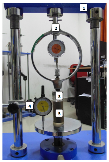
- Loading frame of capacity of 2 t, with constant rate of movement
- Proving ring of 0.01 kg sensitivity for soft soils; 0.05 kg for stiff soils
- End platen of required diameter made with perspex glass (diameter of the platen is selected according to the diameter of the sample)
- Dial gauge (0.01 mm accuracy)
- Soil sample of 38 mm diameter & 76 mm length

Specimen Preparation:
In this test, a cylindrical specimen of soil with aspect ratio 2 without lateral support is tested to failure in simple compression, at a constant deformation rate (1.25 mm/min, 2.25 mm/min, 2.5 mm/min). The compressive load per unit area required to fail the specimen is called unconfined compressive strength of the soil.
a) Undisturbed Specimen(UDS):
- Note down the sample number, bore-hole number and the depth at which the sample was taken.
- Remove the protective cover (paraffin wax) from the shallby tubes.
- Place the sampling tube extractor and push the plunger till a small length of sample moves out.
- Trim the projected sample using a wire saw, and push the plunger until a sample larger than required length comes out.
- Cutout this sample carefully and hold it on the split sampler so that it does not fall and trim the specimens to required height.
- Take about 10 to 15 g of soil from the tube for water content determination.
- Measure the diameter at top, middle, and bottom of the sample. Find the average and record the same.
- Measure the weight of the sample and record.
If the extracted sample has cracks, it can not be used for testing. Remolded specimens at in-situ density and water content needs to be prepared to conduct UC test.
b) Remoulded Specimen(R):
- For the desired water content and the dry density, calculate the weight of the dry soil Ws required for preparing a specimen of 38 mm diameter and 76 mm long.
- Add required quantity of water Ww to this soil.
Ww = Ws x W/100 gm - Mix the soil thoroughly with water.
- Divide the wet soil into equal parts same as the number of the layers in which the soil is to be compacted.
- Apply silicon spray coating on the inner side of split mold and bottom plate of mold.
- Place the soil required for one layer in the split mold arrangement with bottom cap and collar.
- Compact the soil using the cylindrical block and rammer until the required height of layer is achieved.
- Check the height of the layer using the markings on the cylindrical block.
- Scratch the layer before placing the soil for next layer to assure the proper bonding between two layers.
- Repeat steps 7-9 for each layer until required height of specimen is achieved.
- Extract the specimen from the split mold.
- Record the height, weight and diameter of the specimen.
Experimental procedure (IS 2720 Part 10):
- Place the bottom platen on the loading frame and then place the specimen on bottom platen.
- Place the top cap on the specimen and a steel ball on the circular impression of top cap.
- Adjust the center line of the specimen such that the proving ring and the steel ball are in the same line.
- Fix a dial gauge to measure the vertical compression of the specimen.
- Adjust the gear position on the load frame to give suitable deformation rate. The deformation rate of 1.25 mm/min is commonly used to conduct the UC test on soil specimens of 38 mm diameter.
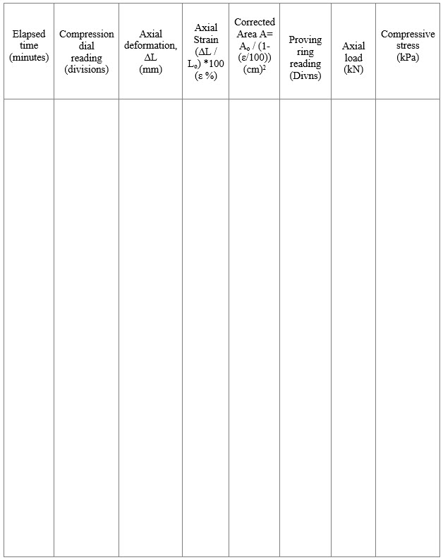
- Start applying the load and record the readings of the proving ring and compression dial for every 25 dial gauge reading.
- Continue loading till failure or 20% axial strain (whichever is reached earlier) (IS-2720-PART-10-1991), and then take the picture of the failure pattern of the specimen.
- Repeat the procedure for atleast three specimens.
Unconfined Compression (UC) Test
Observation Sheet:
Type Undisturbed/Remoulded:
Dry density = _____________ g/cc
Water content (%) = ______
Degree of saturation = _______ %
Diameter (Do) of the sample ______ cm
Area of cross-section = _______ cm2
Initial height (Lo) of the sample =______ cm
Proving ring constant = _______
Dial gauge constant = _______mm
Deformation rate= __________ mm/min

Calculations:
- Axial stress = (Proving ring reading x Proving ring constant) / Acorr
- Acorr= A0/(1-ε); A0 is initial cross-sectional area of the soil specimen, ε is the axial strain at that point of loading.
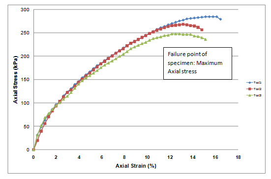
- Maximum axial stress is obtained, which is also considered to be the failure point of the specimen.
- Repeat the test 3 times. Find the average value of maximum axial stress obtained in all three UC tests.
- Unconfined compression strength of the soil, qu = average value of maximum axial stress of three tests
- Shear strength of the soil (cohesion, c) = qu/2
- Sensitivity = (qu for undisturbed sample)/ (qu for remoulded sample).
Unconfined Compression (UC) Test
Graphs:
1. Axial stress versus Axial strain relationship
Example:

The UC test has been performed at loading rate of 1.25mm/min on specimen of 38 mm dia & 76 mm ht.
Results:
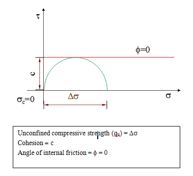
Unconfined Compressive Strength (qu) = 267 kPa
Cohesion (c) = 133 kPa
Internal friction angle (Φ) = 0 deg
Unconfined Compression (UC) Test
Theory:
In UC test, a cylindrical soil specimen of standard size (normally 38 mm dia & 76 mm ht) is loaded axially monotonically under compression till failure at a constant strain rate / deformation rate in a loading frame. Since soil specimen is not kept laterally confined, it is termed as Unconfined Compression test. The axial/vertical compressive stress is the major principal stress and other two principal stresses are considered to be zero.
Since soil specimens are kept unconfined, these tests cannot be performed on soils which cannot stand without lateral support. These tests are performed only on cohesive soils in undisturbed or remoulded conditions. A loading frame with proving ring and a dial gauge to measure axial load and axial deformation, respectively. Maximum axial stress (compressive stress) causing failure is obtained from stress-strain plot and is defined as unconfined compressive strength of soil. When failure point on the curve is not defined, the stress corresponding to 20% axial strain is used to represent the strength values. During the test, No drainage of water from the sample takes place; and to maintain same water content of the sample, the test is run at a fast strain rate. Failure plane is not predetermined and takes place along the weakest plane.
Mohr circle of stresses at failure in unconfined compression test and loading conditions are given below:

