Direct Shear Test
Need and Scope:
The value internal friction angle and cohesion of the soil are required for design of many engineering structures such as foundations, retaining walls, bridges, sheet piling. Direct shear test can predict these parameters quickly.
Concept:
The concept of direct shear is simple and mostly recommended for granular soils, sometimes on soils containing some cohesive soil content. The cohesive soils have issues regarding controlling the strain rates to drained or undrained loading. In granular soils, loading can always assumed to be drained. A schematic diagram of shear box shows that soil sample is placed in a square box which is split into upper and lower halves. Lower section is fixed and upper section is pushed or pulled horizontally relative to other section; thus forcing the soil sample to shear/fail along the horizontal plane separating two halves. Under a specific Normal force, the Shear force is increased from zero until the sample is fully sheared (failed). The relationship of Normal stress and Shear stress at failure gives the failure envelope of the soil and provide the shear strength parameters (cohesion and internal friction angle).
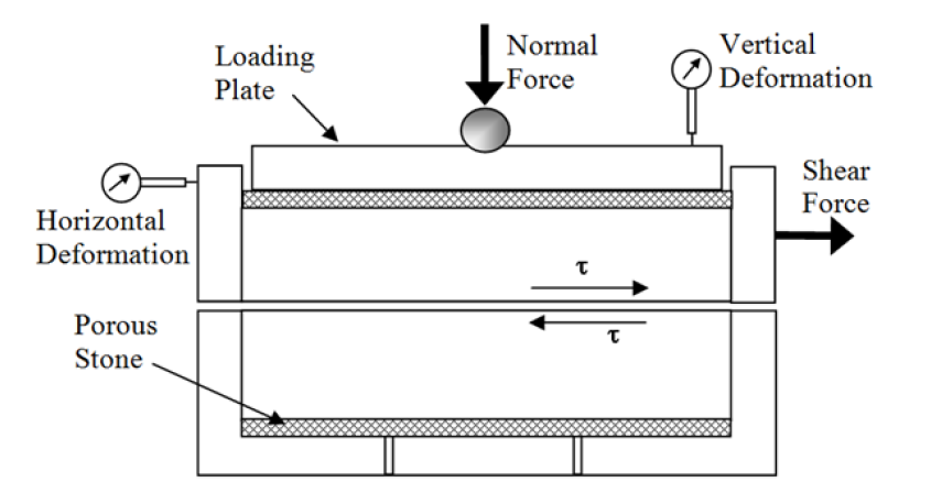
Direct Shear Test
Experimental Setup:
Strain controlled direct shear machine consists of shear box, soil container, loading unit, proving ring, dial gauge to measure shear deformation and vertical deformation (volume changes). A proving ring is used to indicate the shear load taken by the soil along the shearing plane.
- Direct shear box apparatus, and Loading frame (motor attached)
- Dial gauge for vertical deformation measurement
- Dial gauge for horizontal deformation measurement
- Proving ring for Shear force measurement. Loads are kept in loading frame for application of Normal stress
- Components of shear box with porous stone, filter paper, two corrugated metallic plates with perforation (drained) and without perforation (undrained), metallic pressure pad etc.
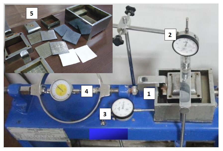
Testing Procedure (IS 2720 Part 13):
- Take the measurements of inner dimension of the soil sampler, and put the parts of the shear box together.
- Calculate the volume of sampler and take the weight of sampler.
- Place the soil inside the sampler in three smooth and equal layers. If the dense sample is desired, tamp the soil with appropriate equal number of blows in each layer for the required density.
- After completing three layers, level the top layer and weigh the soil sampler with soil. Find the weight of wet soil and calculate the density of soil to confirm whether the required density is achieved.
- Place the base plate in the shear box and perforated grid plate (for submerged condition) over it in such a way that the serrations of the grid plate are perpendicular to the direction of shear. Then, put the filter paper and place the soil specimen over it.
- Lock the upper and lower half of the shear box with locking screws. After locking, place the upper filter paper, perforated grid plate, porous stone, and loading pad sequentially on the top of soil.
- Create a small gap of approximately 1 mm between two parts of the shear box using spacing screws.
- Place the whole assembly in the box of the loading frame and put the loading yoke on top of the loading pad.
- Adjust the dial gauges and proving ring to zero position after setting up the specimen set up. Apply the desired normal stress say, 0.5 kg/cm2, add water (if soaked condition) at the top of the direct shear box set up, and wait for at least 20 minutes to ensure saturation (until the reading in vertical dial gauge becomes constant) and then remove the locking screws.
- Measure the final vertical dial gauge reading which measures the deformation in the vertical direction due to saturation.
- Record the initial reading of the horizontal dial gauge and proving ring values before starting the shearing.
- Check all adjustments to see that there is no connection between two parts except soil.
- Set the strain-controlled frame to the required strain rate. Start the motor. Take the reading of the shear force in the proving ring with respect to the change in horizontal dial gauge reading and vertical deformation in vertical dial gauge till failure.
- The steps from 1 to 13 have to be repeated for another two normal stresses (1.0 kg/cm2 and 1.5 kg/cm2).
Direct Shear Test
Observation Sheet:
Size of the sample = 60 mm x 60 mm x 25 mm
Area of the sample (Cross Sectional ) = 36 sq.cm
Volume of the sample = 90 cm3
Weight of the sample (gm) =
In-situ Density of the sample (gm/cc) =
In-situ water content (%) =
Least count of dial gauge (Horizontal) =
Least count of dial gauge (Vertical) =
Proving Ring No. =
Proving ring constant =
Normal stress (Kg/ sq.cm) =
Normal stress = (Applied Normal Load x Lever Ratio) / Cross sectional Area of sample
Test 1: Applied Normal Stress = 0.5 kg/cm2
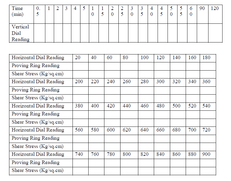
Test 2: Applied Normal Stress = 1.0 kg/cm2
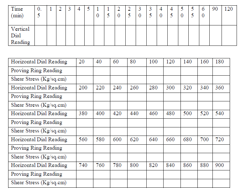
Test 3: Applied Normal Stress = 1.5 kg/cm2
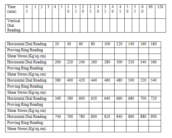
Calculations:
- Shear stress (τ) on the horizontal failure plane is calculated as τ = S/A; Where S is shear force. A is the horizontal cross-sectional area of the sample, which decreases slightly with the horizontal deformations.
- Corrected area (Acorr) needs to be calculated for calculating the shear stress at failure. Acorr = A0*(1-δ/6), where δ is horizontal displacement due to the shear force applied to the specimen. A0 is the initial area of the soil specimen. A0 and δ are in cm.
- i. Shear Stress = (Proving ring reading x Proving ring constant)/Acorr
ii. Horizontal displacement = Horizontal dial gauge reading x Least count of horizontal dial gauge
iii. Vertical displacement = Vertical dial gauge reading x Least count of vertical dial gauge - Shear stress at failure needs to be calculated for all three tests performed at three different normal stresses to plot the failure envelope.
Direct Shear Test
Graphs:
- Shear stress Vs Horizontal displacement relationship for tests performed at Normal Stress of 0.5, 1.0 & 1.5 kg/cm2
- Shear stress Vs Normal stress (Failure envelope).
Shear stress Vs Horizontal displacement curve
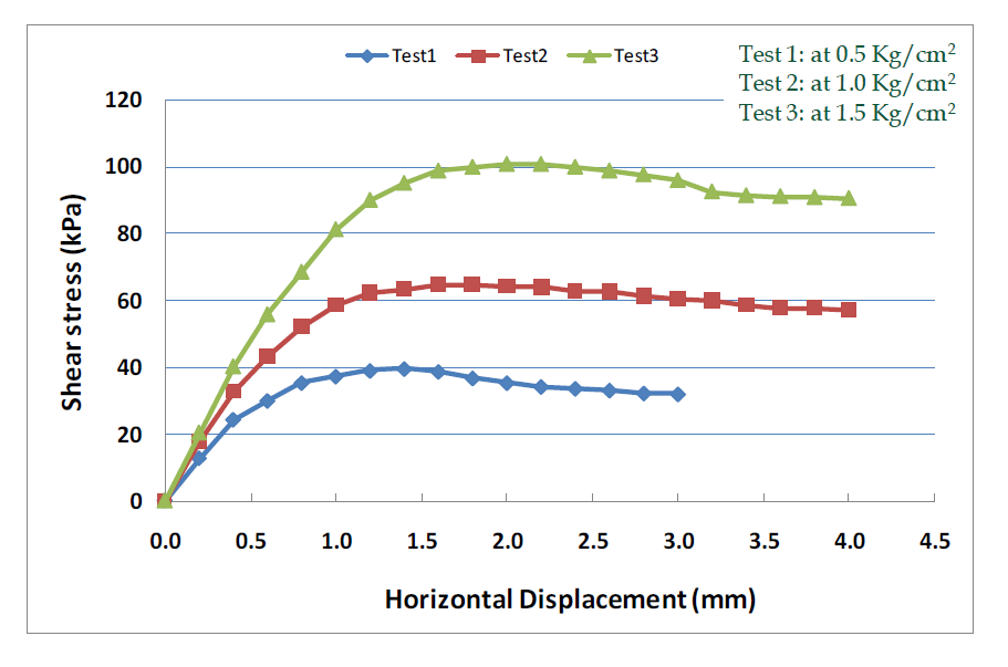
Shear stress data at failure for tests at Normal Stress of 0.5, 1.0 & 1.5 kg/cm2

*All three tests were performed at deformation rate =0.25mm/min
Shear stress Vs Normal stress (Failure envelope)
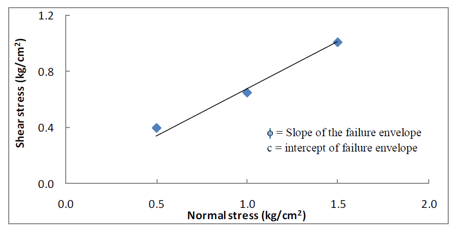
Shear strength parameters of soil
Cohesion (c) = 0 kPa
Internal friction angle (Φ) = 34 deg
General Remarks
- In the shear box test, the specimen is not failing along its weakest plane but along a predetermined or induced failure plane, i.e. horizontal plane separating the two halves of the shear box. This is the main draw back of this test. Moreover, during loading, the state of stress cannot be evaluated. It can be evaluated only at failure condition, i.e Mohr’s circle can be drawn at the failure condition only. Also failure is progressive.
- Direct shear test is simple and faster to operate. As thinner specimens are used in shear box, they facilitate drainage of pore water from a saturated sample in less time. This test is also useful to study friction between two materials – one material in lower half of box and another material in the upper half of box.
- The angle of shearing resistance of sands depends on state of compaction, coarseness of grains, particle shape and roughness of grain surface and grading. It varies between 28 deg (uniformly graded sands with round grains in very loose state) to 46 deg (well graded sand with angular grains in dense state).
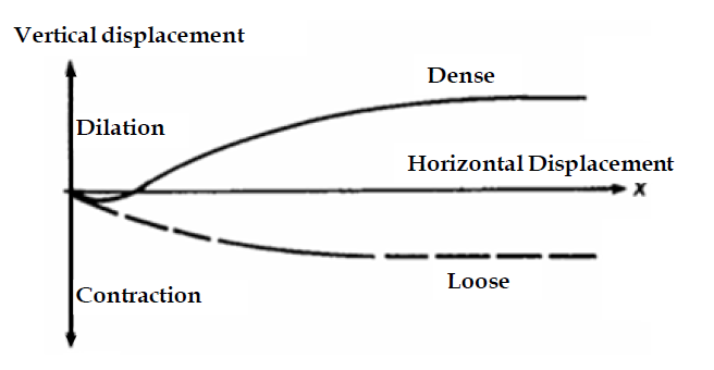
- The volume change in sandy soil is a complex phenomenon depending on gradation, particle shape, state and type of packing, orientation of principal planes, principal stress ratio, stress history, magnitude of minor principal stress, type of apparatus, test procedure, method of preparing specimen, etc. In general, loose sands contract and dense sands expand in volume on shearing. Expansion or contraction can be inferred from the movement of vertical dial gauge during shearing.
- The friction between sand particle is due to sliding and rolling friction and interlocking action.
The ultimate values of shear parameter for both loose sand and dense sand approximately attain the same value so, if angle of friction value is calculated at ultimate stage, slight disturbance in density during sampling and preparation of test specimens will not have much effect.
Direct Shear Test
Theory:
In direct shear test, square/rectangular specimens are used unlike most of the other shear strength tests. Cylindrical (Circular) specimens are used in most of the shear strength tests such as Triaxial, UC test etc. Both shapes of specimen have their own pros and cons. In square/rectangular specimen, it is easy to calculate the magnitude of qualitative shear stress along the surface, whereas in circular section, we get uniformity of shear stress in the specimen.
When soil sample is subjected to horizontal load, stresses are also produced at the vertical boundaries. However, vertical sides are normally greased in direct shear setup to prevent any shear stress at these boundaries during normal stress application stage and this lubrication presumably carries over to the shearing stage at given normal stress. Hence, no shear stress can exist at both vertical and horizontal surface, and consequently the shearing stresses must also be non-uniform on the horizontal faces.
In direct shear test, strain responsible for shear resistance is different from displacement between the two halves divide by specimen thickness because most of the distortion occurs in a thin zone of unknown thickness. Therefore, it is not easy to calculate other than qualitative stress-strain data from the test.
Since only normal and stress stresses can be calculated through this test, it is difficult to draw Mohr circle giving state of stresses. However, by drawing a perpendicular to failure envelope at a particular normal stress, a semi-circle can be plotted. Its center will be point on normal stress axis(x-axis) cut by perpendicular line which represents the radius of semi-circle.
The porous stone is not needed for tests on dry soils, but it is very essential for tests on moist or saturated soils. Mostly, shear strength of soil is measured under Wet condition (moist sample) in Direct shear test.
Change in volume is directly proportional to change in thickness of soil sample since cross-sectional area remains constant. Dense soils usually show contraction initially, and then dilate (expand in volume); however, loose soils show only contractive (decrease in volume) response; as shown below.
Limitations
- It is difficult to control the drainage conditions.
- Lateral pressures and stresses on planes other than the plane of shear is not known.
Pore water pressure cannot be measured. - The shear failure plane is predefined which might not be weakest one.
- Shear stress distribution on the failure plane is non-uniform.
- The contact area between the soil and in the two halves of the box decreases as the test proceeds.
- Field conditions cannot be simulated.
The direct shear can be used to measure the shear strength parameters at the interface of soil and foundation material by keeping the foundation material in the bottom half and the soil can be placed above it.
