Desiccation Cracking Test
Need and Scope:
Desiccation cracks are commonly observed in compacted geotechnical structures such as clay liners, earthen embankments, covers for waste repositories, canal slopes, etc. The occurrence of such cracks significantly changes the hydraulic conductivity and deteriorates the mechanical behavior and durability of the structures. Studying the evolution of desiccation cracking morphology and its underlying mechanism becomes essential for:
- Suitable selection of fill-materials for designing stable clay liners, embankments, etc.
- Predicting changes in permeability and contaminant transport.
- Developing constitutive models that couple drying, shrinkage and fracture.
Concept:
A desiccation test typically monitors a soil specimen undergoing controlled drying while capturing high-resolution images and surface deformation data to characterize the onset and evolution of tensile cracks. It provides both morphological descriptors (crack area, crack length, crack width, etc.) and kinematic information (strain localization maps) which are obtained from the combined use of digital image analysis (DIA) and digital image correlation (DIC). These two image processing techniques link crack geometry with localized strain patterns and allow objective comparison between specimens and also help in suggesting suitable treatment methods.
Desiccation Cracking Test
Test Setup and Accessories:
-
-
- Desiccation simulation chamber
- High-resolution DSLR camera (Canon EOS 1300D-18 megapixel with 72 dots per inch) with a mounting tripod
- Automated image acquisition system with real-time image monitoring facility
- A pair of incandescent bulbs (60W)
- A mini-electrical fan
- A pair of soft light boxes
- Magnetic digital-weighing balance (± 0.01g)
- Thermo-hygrometer
-
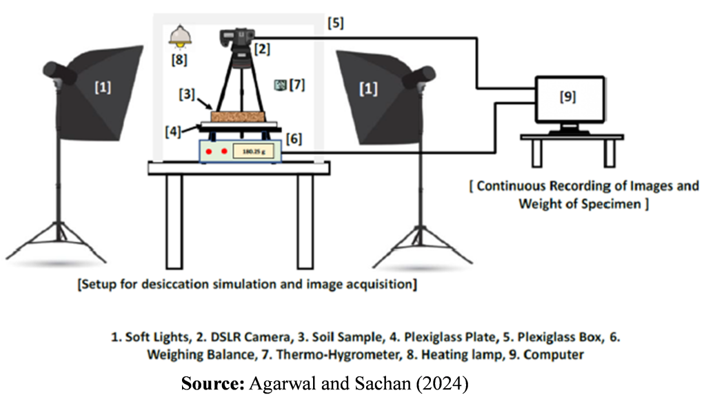
Fig 1. Schematic diagram of desiccation cracking test apparatus and accessories
Testing Procedure:
- The test specimen (100 mm diameter and 20 mm height) is prepared using static compaction method with a deformation rate of 1 mm/min.
- The top surface of the compacted specimen is carefully trimmed and levelled using a blunt knife to obtain a smooth, horizontal surface for clear crack visualization.
- A random speckle pattern is applied to the smoothened top surface using white matte-finish spray paint, to enable DIC.
- The required climatic conditions in the test chamber are to be ensured before the start of the experiment.
- The specimen is placed on the digital weighing balance and a scale patch with known grid spacing, is kept on the specimen surface to capture a scaling image for DIA calibration.
- After capturing the scaling image, the patch is removed and the camera is switched to manual focus mode for uninterrupted image acquisition. The mini-fan is switched on to aid moisture evaporation and moisture loss data is recorded continuously using a data logging software (Terminal v1.93b).
- Images of the desiccating surface are captured at 2-minute intervals for at least 24 hours which are used for further image processing as described in the Data Analysis section.
Desiccation Cracking Test
The quantification of morphological features using DIA is performed using ImageJ software, following these steps:
- The scaling image is opened in ImageJ, and a line segment is drawn between two nearest grid points using the straight-line tool. The segment length is set equal to the known dimension of the scale patch and made globally applicable to ensure consistent and accurate crack measurements.
- The first image after the onset of desiccation is used to define the Region of Interest (ROI). A circular ROI of 98 mm diameter is drawn using the oval selection tool, converted into a mask, and applied to crop all raw images through batch processing. A Python script may be used to extract images at required time intervals (say 10-minute intervals) to reduce the computational load without compromising the accuracy of the analysis.
- All cropped images are converted from RGB to 8-bit grayscale format.
- Manual thresholding is performed to isolate cracks (black pixels, intensity 0) from the uncracked background (white pixels, intensity 255), producing binary images.
- Binary operations (OPEN, CLOSE, and FILL HOLES) are applied to remove noise, smooth crack boundaries, and fill small gaps or holes.
- A circularity filter with a suitable threshold is applied to remove spurious circular objects, retaining only features with lower circularity typical of cracks. The final processed images are post-processed in order to quantify the morphological crack parameters.
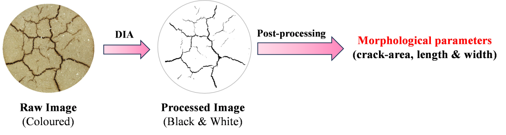
Fig 2. Typical morphological parameters quantified using DIA
The quantification of strain localization using DIC is performed using Ncorr software, following these steps:
- The reference image, captured immediately before desiccation, is loaded in Ncorr.
- The required number of successive crack images (say first 240), each at 2-minute intervals are selected as current images in order to minimize deformation between successive frames.
- The ROI mask created during DIA is loaded and applied as the reference ROI in Ncorr.
- DIC parameters are set to default values: subset radius 123 pixels, subset spacing 10 pixels, iterative solver tolerance 10⁻⁶, 50 iterations, and four threads for multithreading. Auto seed propagation is enabled to prevent error propagation when shrinkage occurs.
- Four seeds are placed at the center of each quadrant within the ROI to initiate analysis, and their placement is verified for convergence and correlation quality before execution.
- Displacements along the X (u) and Y (v) axes are converted from pixels to millimeters using the scaling factor obtained from DIA, and noisy points are filtered using the default correlation coefficient cutoff.
- Strains are calculated from displacement data using a least-squares plane fit, and a strain radius of six pixels is applied, with adjustments made in high-deformation regions if required.
- Color maps of Green-Lagrange strains (εxx, εyy, and εxy) are generated with fixed strain magnitude bounds for each specimen to allow consistent visualization of strain evolution over time.
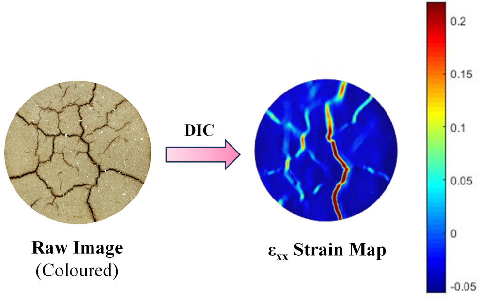
Fig 3. Typical strain map generated from digital images using DIC
Desiccation Cracking Test
Cracking Morphological Parameters obtained using DIA Technique:
- The total number of black pixels in the processed image (representing the total crack area) are counted which are converted into surface area values (using a pre-determined scaling factor) in order to evaluate the total crack area.
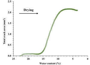
Fig 4. Evolution of total crack area with decreasing water content

Fig 5. Evolution of total crack length with decreasing water content
- The average crack width is evaluated as the ratio of the total crack area to the total crack length.

Fig 6. Evolution of average crack width with decreasing water content
Strain Localization Parameters obtained using DIC Technique:
- The strain localization map provides insights into the spatiotemporal evolution of strains across the desiccating soil. It can also capture the formation of micro-cracks that may otherwise go undetected by solely relying on DIA technique.
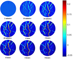
Fig 7. Spatiotemporal evolution of εxx
- Principal strain fields are used to study the different modes of cracking viz. tensile, shear or mixed modes of cracking w.r.t. the perpendicular, parallel or mixed orientation of the major principal strain vectors with the direction of crack propagation.
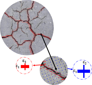 Fig 8. Desiccation cracking under shear mode represented using the principal strain map
- Displacement vector fields are used to study the surface deformation trends, tessellation tendencies and identify shrinkage centers.
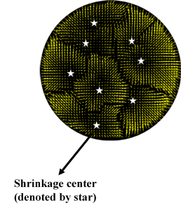
Fig 9. Representation of shrinkage centers using the displacement vector field
Desiccation Cracking Test
Theory:
Desiccation cracking is a natural phenomenon that occurs in drying clayey soils when the tensile stresses induced by evaporation exceed the soil’s inherent tensile strength. During drying, evaporation from the soil surface reduces pore water pressure, increasing matric suction within the unsaturated zone. This suction generates differential shrinkage strains, which, when restrained by interparticle bonding and boundary conditions, lead to the accumulation of tensile stresses. Once these stresses surpass the soil’s fracture resistance, cracks initiate and propagate. The fracture process in clayey soils is strongly influenced by soil mineralogy, clay content, initial water content, dry density, and the soil-water characteristic curve. Capillary forces, particle orientation, and interaggregate bonding dictate both the initiation threshold and the progression rate of cracking. As cracks widen and connect, a polygonal network often develops, characterized by parameters such as surface crack ratio, total length, average width, number of crack segments, connectivity index, etc. Desiccation cracking significantly modifies the mechanical and hydraulic properties of soils. The presence of cracks increases permeability, facilitates preferential flow, and reduces overall shear strength. In geotechnical contexts, this can adversely affect the performance of earthen structures such as embankments, liners, and slopes. Understanding the mechanisms and controlling factors of desiccation cracking is therefore essential for accurate prediction, modeling, and mitigation in geotechnical engineering practice.
References:
- Agarwal, B. K., Sachan, A., 2024. Quantification of desiccation cracking and strain localization in lime-treated compacted expansive soils using DIA and DIC. Journal of Materials in Civil Engineering. 36(2), p.04023541. https://doi.org/10.1061/JMCEE7.MTENG-16352.
- Majumder, S., Agarwal, B. K., & Sachan, A., 2025. Desiccation cracking and strain localisation response of compacted clays with varying plasticity using DIA and DIC. Geomechanics and Geoengineering, 1-22. https://doi.org/10.1080/
17486025.2025.2594568