Stress Path(SP) Triaxial Test
Need and Scope:
Stress-path triaxial test is performed to determine the effect of stress induced anisotropy on the shear behavior of soil. Anisotropic consolidation simulates the field conditions more accurately. The soil specimens are consolidated anisotropically and then sheared under constant rate of axial strain in either compression or extension. This test can be done in drained as well as undrained conditions.
Concept:
Stress path triaxial tests can be performed on any type of soils. The specimen is allowed to consolidated under the anisotropic condition for the applied target stresses. The anisotropic condition is generated by applying the unequal radial and axial stresses (σr ≠ σa) during the consolidation phase of triaxial testing. The values of target radial and axial stresses are calculated based on the required anisotropy value (Kc). Anisotropy value is defined as the ratio of effective radial to effective axial stress (Kc = σr’/σa’). After completion of anisotropic consolidation, specimen is sheared by applying deviatoric stress at constant axial strain rate. The drainage valve can be opened or closed based on the required drainage conditions as drained or undrained, respectively.
Stress Path(SP) Triaxial Test
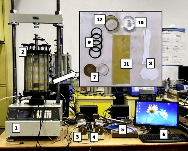
Experimental Setup:
- Loading frame of capacity of 10 t, with constant rate of movement.
- Triaxial cell
- Pore water pressure transducer
- Volume change transducer
- Data acquisition system
- Computer with Triaxial testing software
- Porous stone
- Filter paper
- O-rings
- Specimen end platen (Perspex plate with silicon grease coating)
- Latex membrane
- Latex cap (to create vacuum between end platen and load cell for anisotropic consolidation)
Testing procedure:
Saturation phase:
- The saturated porous stone disc of diameter same as the sample is placed on top of the pedestal of triaxial testing machine and the circular filter paper of same size is placed over the disc. Specimen is placed on top of the filter paper. The filter paper with porous stone is placed on the top of the specimen to allow two-way drainage.
- The latex membrane is stretched in the membrane stretcher and placed on the soil specimen. O rings are placed at top and bottom of platens of the soil specimen to prevent the cell water entering into the specimen.
- The triaxial cell is placed over the base and tightened with the screws. The cell is then filled with water and a small confining pressure of about 10 kPa is applied to hold the specimen in place.
- The soil specimen needs to be completely saturated before isotropic consolidation phase.
- Saturation process consists of three steps: i) CO2 saturation, ii) Water saturation, iii) Back pressure application.
- CO2 is applied continuously for minimum 3-6 min from bottom of the specimen and then allow it to go out of the specimen from the top. CO2 replaces the air in void space of the specimen which gets easily dissolved in the water present within the specimen. The CO2 flushing process is repeated 4-5 times to ensure better saturation.
- Water saturation is done by supplying water from bottom of the specimen and allow it to go out of the specimen from the top to do proper water flushing of the specimen. The water used for flushing needs to be distilled & de-aired water.
- The force saturation is performed by applying cell pressure and the back pressure at constant increments with constant difference between these two pressures. The sample is allowed to saturate for some time (10-20 min) after each increment of cell pressure and the back pressure. This increase should be followed by a check for saturation value (B), also known as skempton’s pore pressure parameter. It is important to note that cell pressure always be higher than back pressure. The sample is said to be fully saturated if the B value is greater than 0.95 can be acquired.
Anisotropic consolidation phase (Kantesaria and Sachan, 2019):
- Stress path module of automated K stress path triaxial system was used to apply anisotropic consolidation in the specimen. The values of target shear stress (q) and mean effective stress (p’) was calculated based on required stress anisotropy value (Kc = σr’/σa’) as given below and provided as a input in the module.

- The test duration can be controlled by providing constant axial strain rate or by directly specifying time to reach the targeted values. The test duration is chosen such that no excess pore water pressure can developed during the entire process of anisotropic consolidation.
- Drainage valve is kept open and the volume change is measured until no change in volume is observed (when primary consolidation is over).
Shearing phase:
- In the Consolidated Undrained (CU) triaxial test, no drainage is allowed during shearing stage and pore pressure is measured throughout the test using the pore pressure transducer. In the Consolidated Drained (CD) triaxial test, drainage valves are kept open during shearing stage and volume change is measured throughout the test using the volume change transducer.
- The machine is set in motion at an appropriate strain rate based on the soil type. Data acquisition system (DAQ) is attached with the computer & various transducers of triaxial system, which records the data with the help of triaxial CU/CD software. The experiment is stopped at around 15% axial strain.
Stress Path(SP) Triaxial Test
- The data analysis for the anisotropically consolidated undrained triaxial test is similar to CU triaxial test.
- The data analysis for the anisotropically consolidated drained triaxial test is similar to CD triaxial test.
Stress Path(SP) Triaxial Test
Graphs:
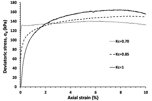
- Deviator stress versus axial strain curve
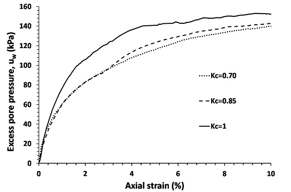
- Excess pore water pressure versus axial strain curve
- Effective stress path (q-p’) curve
Example:
CU tests have been performed on clay specimens at three different Kc ratios (Kc = 0.7, 0.85, & 1) at same mean effective pressure (p’) of 300 kPa before shearing.. All the tests were performed on Normally consolidated (NC) soil specimens.
The specimens were sheared at a strain rate of 0.05% per min after anisotropically consolidating the specimen at achieved confining pressure. In all the tests, the saturation value B was obtained to be 0.96 before starting the consolidation phase.
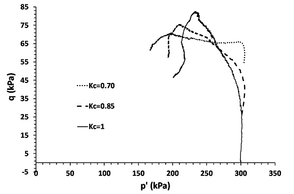
Results:
Results can be analyzed in terms of the effect of variation in anisotropy values on the shear behavior of soil in terms of stress-strain and volumetric response.
General Remarks
- The anisotropic consolidation process must be started after ensuring the saturation value (B) to be more than 0.95.
- The anisotropic consolidation phase in CU/CD testing is applied with the drainage valve open to allow the change in void ratio of saturated soil specimen. The change in void ratio occurs due to the removal of pore water from the soil specimen during anisotropic consolidation process.
- The excess pore water pressure or volumetric strain shows positive values for NC (normally consolidated) soil specimens and negative values for OC (overconsolidated) specimens indicating contractive and dilative response respectively for saturated soils.
- The strain rate must be chosen carefully for CU test based on the soil type. The fine grained soils require to be sheared at much lower strain rate (0.05% per min – 0.2% per min) as compared to the coarse grained soils (0.5% per min – 1% per min). Fine grained soil has lower permeability (lower void space), thus pore water pressure distribution will not be uniform at higher strain in such soils (clay, silt). CD tests are performed at much slower strain rate as compared to CU tests for the same soil. The strain rate for CD test can be chosen approx 8-10 times lower than the CU test.
- Filter paper strips can also be used around the cylindrical surface of the soil specimen to allow radial drainage to improve the drainage conditions, specially in clayey soils.
Stress Path(SP) Triaxial Test
Theory:
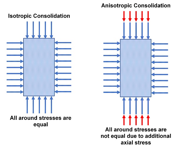
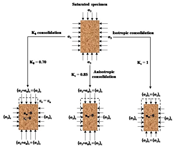
The actual stress conditions on the site while construction of geotechnical structures are not isotropic in nature. This means that the principal stresses acting on the soil structure are not equal from all sides. The microstructure of soil is very much dependent on the acting stress system on it and it changes very much from isotropic to anisotropic condition. Hence, the aim of the stress path triaxial ing is to evaluate the effect of anisotropy on stress-strain and pore-pressure response of soil under drained or undrained conditions.
The difference between isotropic and anisotropic consolidation in terms of acting stress states are explained in figure below. As seen in the figure, stresses from both the radial and axial directions are same (σr = σa) in the case of normal isotropic consolidation. Whereas, the axial stress and radial stress are not equal (σr ≠ σa) during the consolidation for the anisotropic case. K0 consolidation is a special case of anisotropic consolidation. In the case of K0 consolidation, the radial strain during the consolidation remained zero (εr = 0). In K0 stress path testing, the lateral strain (εr) was maintained as zero by keeping volumetric strain (εv) equal to axial strain (εa) (εv=εa) by adjusting the axial load by automated loop system. Shearing stage is started after the consolidation process is over.
Shear deformation stage of anisotropically consolidated soil specimen shows excess pore pressure (u), which exhibits the pore pressure evolution within the soil mass due to load subjected to specimen at applied strain rate for the CU tests. Whereas, in the case of CD tests, volumetric strain response is observed due to applied shearing.
Reference:
Kantesaria N. and Sachan A. (2019). “Effect of anisotropy on stress-strain and pore pressure response of normally and heavily over consolidated Nagpur expansive soil”, International Association for Computer Methods and Advances in Geomechanics (IACMAG) Symposium 2019, Gandhinagar, Gujarat, India, March 5-7, 2019.