Unconsolidated Undrained (UU) Triaxial Test
Need and Scope:
Unconsolidated undrained (UU) triaxial test is quick test as compared to consolidated undrained (CU) and consolidated drained (CD) triaxial test. UU test can be performed on any type of soil to determine its shear strength parameters under undrained condition i.e., cohesion (cu) and angle of internal friction (φu). These undrained shear strength parameters are useful in determination of bearing capacity of soil, stability analysis of highway embankments, earthen embankments etc. One of the critical conditions for stability of any slope occurs immediately after construction, which represents the undrained condition. In such conditions, undrained shear strength parameters should be used for stability analysis.
Concept:
Unconsolidated Undrained (UU) triaxial test provides undrained stress-strain response of a cylindrical soil specimen under triaxial compression loading without consolidating the specimen. It also provides the undrained shear strength parameters by performing the tests on different confining pressures. Initially, a confining pressure (σ3) is applied through water around the specimen in triaxial cell. Drainage valve is closed throughout the test, which does not allow the consolidation of the specimen. The specimen is then subjected to shearing by applying the constant rate of deformation under undrained compression loading conditions. Excess pore water pressure is not measured during shearing; hence the shear strength parameters are analyzed in total stress conditions only.
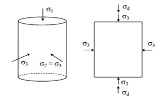
Initial state of stress is hydrostatic with all three principal stresses same as applied confining pressure (σ3). The vertical stress acts as major principal stress (σ1) during shearing, while the confining pressure (σ3) acts in other two principal directions of cylindrical specimen. The intermediate principal and minor principal stresses are equal to each other. Deviatoric stress (σd) is the difference of σ1 (σ1 = σd + σ3) and σ3, acting on specimen while its shear deformation.
Unconsolidated Undrained (UU) Triaxial Test
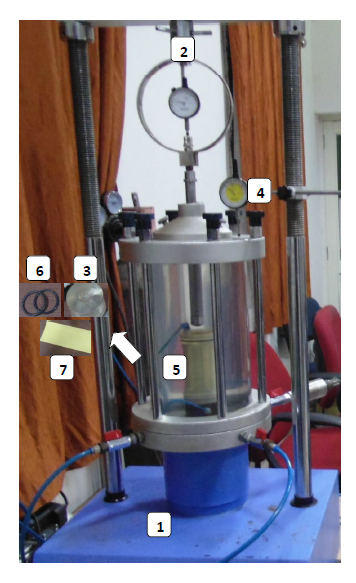
Experimental Setup:
- Loading frame of capacity of 10 t, with constant rate of movement.
- Proving ring of 0.01 kg sensitivity for soft soils; 0.05 kg for stiff soils.
- End platen of required diameter made with Perspex glass (diameter of the platen is selected according to the diameter of the sample)
- Dial gauge (0.01 mm accuracy)
- Soil specimen of 38 mm diameter & 76 mm length
- O-rings
- Latex membrane
Specimen Preparation
The UU triaxial test can be performed on undisturbed soil samples, wherever the undisturbed sample (UDS) collection is possible. When UDS sample collection is not possible or the UDS sample shows cracks while extraction, reconstituted specimens can be prepared. The samples can be reconstituted at in-situ density and moisture content. The UU triaxial test is commonly conducted on specimen size of 38 mm diameter and 76 mm height. The loading frame is used to provide a constant rate of deformation to the specimen commonly 0.4 mm/min for fine soils and 0.6 mm/min for coarse soil.
a) Undisturbed Specimen(UDS):
- Note down the sample number, bore-hole number and the depth at which the sample was taken.
- Remove the protective cover (paraffin wax) from the shallby tubes.
- Place the sampling tube extractor and push the plunger till a small length of sample moves out.
- Trim the projected sample using a wire saw, and push the plunger until a sample larger than required length comes out.
- Cutout this sample carefully and hold it on the split sampler so that it does not fall and trim the specimens to required height.
- Take about 10 to 15 g of soil from the tube for water content determination.
- Measure the diameter at top, middle, and bottom of the sample. Find the average and record the same.
- Measure the weight of the sample and record.
b) Remoulded Specimen(R):
- For the desired water content and the dry density, calculate the weight of the dry soil, WS, required for preparing a specimen of required dimensions (diameter and height)
- Add required quantity of water, ww, to this soil.
WW = WS´ W/100 gm - Mix the soil thoroughly with water.
- Divide the wet soil into equal parts same as the number of the layers in which the soil is to be compacted.
- Apply silicon spray coating on the inner side of split mold and bottom plate of mold.
- Place the soil required for one layer in the split mold arrangement with bottom cap and collar.
- Compact the soil using the cylindrical block and rammer until the required height of layer is achieved.
- Check the height of the layer using the markings on the cylindrical block.
- Scratch the layer before placing the soil for next layer to assure the proper bonding between two layers.
- Repeat steps 7-9 for each layer until required height of specimen is achieved.
- Extract the specimen from the split mold.
- Record the height, weight and diameter of the specimen.
Testing procedure (IS 2720 Part 11):
- Place the bottom platen on the pedestal of base plate of triaxial cell, then place the specimen on bottom platen.
- Place the top cap on the specimen.
- Seal the specimen arrangement properly with the latex rubber membrane and rubber O-rings using the membrane stretcher.
- Place the cell such that it must be properly set up and uniformly clamped down to prevent leakage of pressured water during the test.
- Move down the plunger and set up it on the circular groove of the top cap. Place a steel ball on the top of plunger.
- Adjust the center line of the specimen such that the proving ring, the steel ball, plunger and specimen are in the same line.
- Fill the cell with the water with bleed valve open. Close the bleed valve tightly after filling the cell with water.
- The air water interface is then regulated using valves and regulator of constant pressure system, and the pressure is applied to water with the balloon in interface system. This pressure is applied through water to the cell.
- Open the valve that connects pressure to the cell to apply the required cell pressure. (For example, 50 kPa, 100 kPa and 150 kPa or 100kPa, 200 kPa and 300 kPa as per the depth where the sample is brought and the application requirements.)
- The pressure gauge must be watched during the test and any necessary adjustments must be made to keep the pressure constant.
- A small deformation is applied to the system until the underside of the hemispherical seating of the proving ring, through which the loading is applied, just touches the steel ball on cell piston. This procedure is called the docking of triaxial system.
- After docking fix a dial gauge to measure the vertical compression of the specimen.
- Adjust the gear position on the load frame to give suitable rate of deformation.
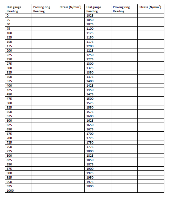
- Start applying the load and record the readings of the proving ring and compression dial for every 25 divisions in compression dial gauge.
- Continue loading till failure or 20% axial strain (whichever is reached earlier) (IS-2720-PART-10-1991), and then take the picture of the failure pattern of the specimen.
Unconsolidated Undrained (UU) Triaxial Test
At particular intervals of strain, dial gauge readings and the corresponding proving ring readings are taken, and the corresponding load is determined using proving ring constant. The experiment is stopped either at failure or at the 20% axial strain.
Observation Sheet:
Test 1: Cell pressure = ___________ kg/cm2
Weight of Sample:___________________ In-situ density: __________________
Diameter:________________________ Area:________________________
Initial Water Content:_________________ Deformation rate:_ _________________
Least count of dial gauge:_______________Proving ring constant: _______________
Test 2: Cell pressure = ___________ kg/cm2
Weight of Sample:___________________ In-situ density: __________________
Diameter:________________________ Area:________________________
Initial Water Content:_________________ Deformation rate:__________________
Least count of dial gauge:_______________Proving ring constant: _______________
Test 3: Cell pressure = ___________ kg/cm2
Weight of Sample:___________________ In-situ density: __________________
Diameter:________________________ Area:________________________
Initial Water Content:_________________ Deformation rate:__________________
Least count of dial gauge:_______________Proving ring constant: _______________
Calculations:
- Acorr = A0/(1-ε); where A0 is initial cross-sectional area of the soil specimen, ε is the axial strain at that point loading. Axial stress = (Proving ring reading x Proving ring constant)/Acorr
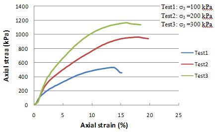
- Axial stress versus axial strain curves are drawn for UU tests performed at three different confining stresses.
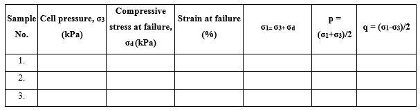
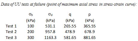
- Deviator stress (σd) at failure needs to be obtained for UU tests for all three confining stresses (σ3). σ1 is the sum of σd and σ3.
- Maximum deviator stress can be considered as the failure point of the specimen in its stress-strain relationship.
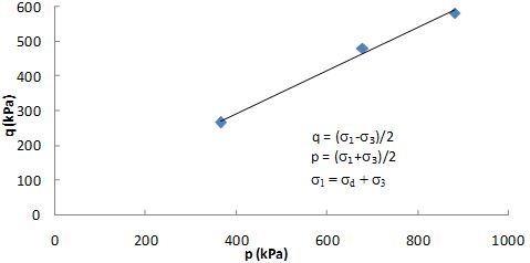
- Modified Failure envelop (q-p curve) is drawn using UU test data, which provides a & ζ parameters. a is intercept of q-p curve and ζ is the slope angle of q-p curve.
q = (σ1 – σ3)/2, p = (σ1 + σ3)/2 - Shear strength parameters (c & Φ) can be calculated by using following equations.
ccosΦ = a, sinΦ = tanζ
Unconsolidated Undrained (UU) Triaxial Test
Graphs:
- Axial stress versus Axial strain relationship
- Modified Failure envelop (q-p) curve
Example:
UU tests have been performed on silty clay specimens at confining pressure of 1.0 kg/cm2, 2.0 kg/cm2, 3.0 kg/cm2. The specimen size was 38 mm diameter & 76 mm height. The specimen was sheared at deformation rate of 0.4 mm/min (strain rate = 0.5% per min). It is important to note that the soil sample in UU test was unsaturated. If saturated soil samples are used, it is mentioned in the analysis.
Results:
Cohesion (c) = 57 kPa
Internal friction angle (Φ) = 38 deg
General Remarks
- It is assumed that the volume of the sample remains constant and that the area of the sample increases uniformly as the length decreases. The calculation of the stress is based on this new area at failure, by direct calculation, using the proving ring constant and the new area of the sample.
- The strain and corresponding stress is plotted with stress abscissa and curve is drawn. The maximum compressive stress at failure and the corresponding strain at different cell pressure are found out.
- The stress results of the series of triaxial tests at increasing cell pressure are plotted as a Modified failure envelope using p = (σ1+σ3)/2 as abscissa and q = (σ1-σ3)/2 as ordinate. In this diagram a best fit line is plotted with in which the slope represents the value of ψ while the intercept represents the value of a.
- From the relation, sinφ = tan ψ, a = c* cosφ;
The value of cohesion, c and the angle of shearing resistance, φ will be determined as the soil shear strength parameters.
Unconsolidated Undrained (UU) Triaxial Test
Theory:
A UU test is carried out almost exclusively on cohesive soils. No drainage is allowed at any stage of the test. The isotropic confining pressure is applied with the drainage valve closed. The entire cell pressure is carried by the pore water, if specimen is saturated. The specimen is loaded under undrained conditions. During the test, there will be pore water pressure development, which is not measured. Therefore, the effective stresses remain unknown. Mohr circles are only drawn in terms of total stresses, which enable the failure envelope to be drawn in terms of total stresses, giving shear strength parameters (cu & Φu) under undrained loading conditions.
Being relatively quick and inexpensive, UU triaxial tests are quite popular in geotechnical engineering practice for obtaining shear strength of cohesive soil. However, this test does not provide the shear strength parameters in terms of effective stresses c’ and Φ’, which are required for carrying out an effective stress analysis.
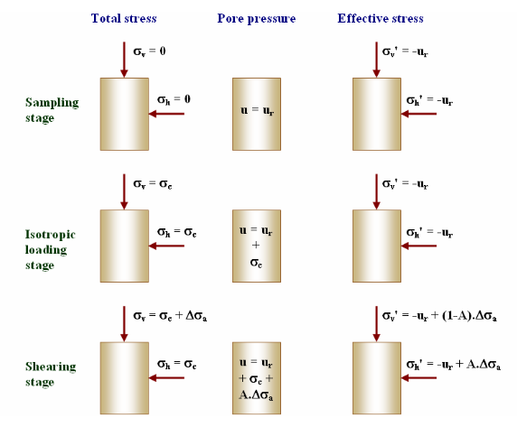
The following sketch shows the three various phases of UU triaxial testing; sampling stage, Isotropic loading stage (application of confining pressure, σ3), Shear stage (application of deviator stress, σd). Total stress, pore pressure and effective stresses are shown at each phase of UU triaxial testing in the given diagram. ur is the residual pore water pressure entrapped inside the soil specimen after its collection from soil site using UDS (Undisturbed sampling) tube. σv and σh are the vertical and horizontal stresses respectively acting on soil specimen during UU triaxial testing. A is the pore pressure parameter due to the shear deformation of the soil specimen.