Consolidated Undrained (CU) Triaxial Test
Need and Scope:
To find the shear strength parameters (c’, Φ’) of soil for effective stress analysis. CU triaxial test is recommended for all types of soil including cohesive and cohesionless soils. Pore pressure evolution with in the soil mass can also be studied in CU tests, along with stress-strain response of soil.
Concept:
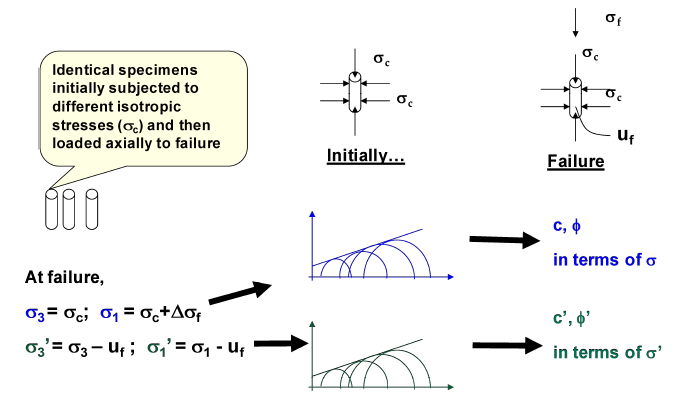
In CU test, drainage is allowed during application of confining pressure (σc) and the specimen is fully consolidated by allowing drainage and it is ensured by observation that no further drainage occurs after sufficient time under the applied pressure. The specimen is then allowed to shear when consolidation is over. During that stage, drainage line is closed and the soil sample is sheared by application of deviator stress (σd; at failure: σd = σf). uf is the pore pressure generated within the soil specimen due to deviator stress at failure. CU triaxial test provides the shear strength parameters for total stress analysis (c, Φ) as well as effective stress analysis (c’, Φ’)
Consolidated Undrained (CU) Triaxial Test
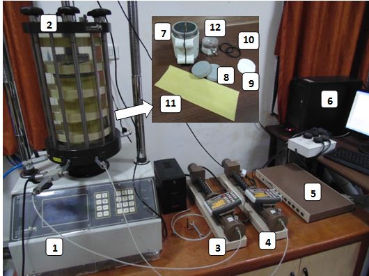
Experimental Setup:
- Loading frame of capacity of 10 t, with constant rate of movement.
- Triaxial cell
- Pore water pressure Transducer
- Volume change transducer
- Data acquisition system
- Computer with Triaxial testing software
- Specimen preparation holder for remoulded specimen
- Porous stone
- Filter paper
- O-rings
- Latex membrane
- Specimen end platen (Perspex plate with silicon grease coating).
Specimen Preparation:
a)Undisturbed Specimen(UDS):
- Note down the sample number, bore hole number and the depth at which the sample was taken.
- Remove the protective cover (paraffin wax) from the sampling tube.
- Place the sampling tube (38 mm dia) extractor and push the plunger till a small length of sample moves out.
- Trim the projected sample using a wire saw, and push the plunger until a 76 mm long sample comes out.
- Cutout this sample carefully and hold it on the split sampler so that it does not fall.
- Take about 10 to 15 g of soil from the tube for water content determination.
- Note the container number and take the net weight of the sample and the container.
- Measure the diameter at top, middle, and bottom of the sample. Find the average and record the same.
- Measure the length and weight of the sample and record.
b) Remoulded Specimen(R):
- For the desired water content and the dry density, calculate the weight of the dry soil Ws required for preparing a specimen of 38 mm diameter and 76 mm long.
- Add required quantity of water Ww to this soil.
Ww = Ws x W/100 gm
- Mix the soil thoroughly with water.
- Place the wet soil in a tight thick polythene bag in a humidity chamber.
- After 24 hours take the soil from the humidity chamber and place the soil in a constant volume mould, having an internal height of 76 mm and internal diameter of 38 mm.
- Place the lubricated mould with plungers in position in the load frame.
- Apply the compressive load till the specimen is compacted to a height of 76 mm.
- Eject the specimen from the constant volume mould.
- Record the correct height, weight and diameter of the specimen.
Testing procedure:
- The saturated porous stone disc of diameter same as the sample is placed on top of the pedestal of triaxial testing machine and the circular filter paper of same size is placed over the disc. Specimen is placed on top of the filter paper. The filter paper with porous stone is placed on top of the specimen to allow two-way drainage. The latex membrane is stretched in the membrane stretcher and placed on the soil specimen. O rings are placed at top and bottom of platens of the soil specimen to prevent the cell water from entering into the specimen.
- The triaxial cell is placed over the base and tightened with the screws. The cell is then filled with water and a small confining pressure of about 10 kPa is applied to hold the specimen in place.
- The soil specimen needs to be completely saturated before isotropic consolidation phase.
- Saturation process consists of three steps: i) CO2 saturation, ii) Water saturation, iii) Back pressure application.
- CO2 is applied continuously for minimum 3-6 min from bottom of the specimen and then allow it to go out of the specimen from the top. CO2 replaces the air in void space of the specimen which gets easily dissolved in the water present within the specimen. The CO2 flushing process is repeated 4-5 times to ensure better saturation.
- Water saturation is done by supplying water from bottom of the specimen and allow it to go out of the specimen from the top to do proper water flushing of the specimen. The water used for flushing needs to be distilled & de-aired water.
- The force saturation is performed by applying cell pressure and the back pressure at constant increments with constant difference between these two pressures. The sample is allowed to saturate for some time (10-20 min) after each increment of cell pressure and the back pressure. This increase should be followed by a check for saturation value (B), also known as skempton’s pore pressure parameter. It is important to note that cell pressure always is higher than back pressure. The sample is said to be fully saturated if the B value greater than 0.95 can be acquired.
- Isotropic consolidation stage is started by applying confining pressure. During the Consolidation stage, drainage valve is kept open and the volume change is measured until no change in volume is observed (when primary consolidation is over).
- In the Consolidated Undrained (CU) triaxial test, no drainage is allowed during shearing stage and pore pressure is measured throughout the test using the pore pressure transducer.
- The machine is set in motion at an appropriate strain rate based on the soil type. Data acquisition system (DAQ) is attached with the computer & various transducers of triaxial system, which records the data with the help of triaxial CU software. The experiment is stopped at around 15% axial strain.
Consolidated Undrained (CU) Triaxial Test
• The three CU tests need to be performed at three different chosen confining pressures.
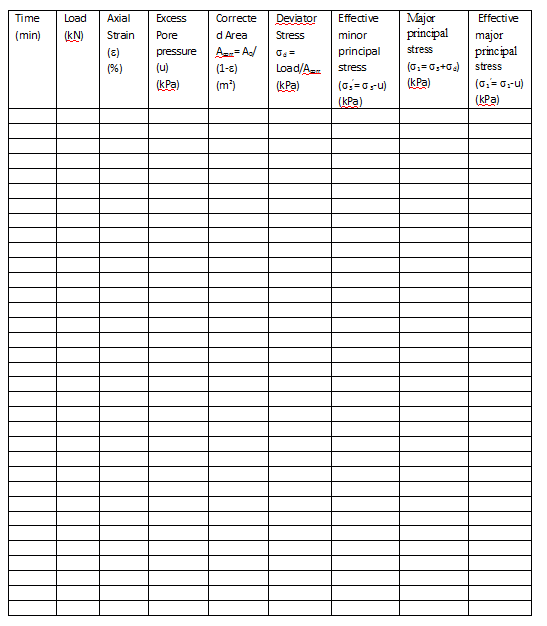
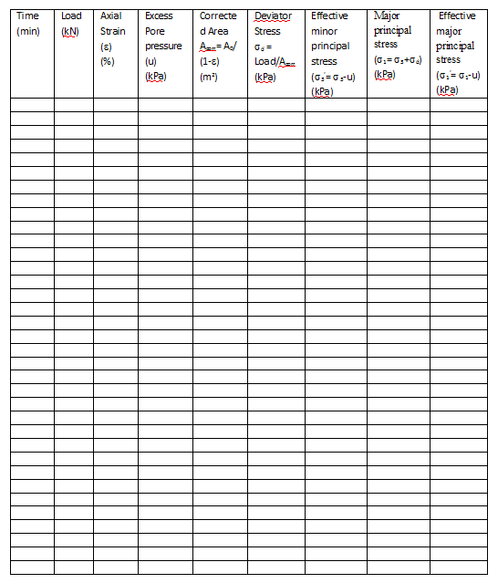
Observation Sheet:
Test 1: Confining pressure = ___________ kPa
Weight of Sample:___________________ In-situ Density: __________________
Initial Water Content:_________________ Strain rate:_ _________________
Diameter:________________________ Height:_________________________
Area(A0):________________________ Volume:________________________
Cell Pressure:_____________________.Back Pressure: ____________________
Confining Pressure (σ3):_______________ Saturation value (B):_______________
Test 2: Confining pressure = ___________ kPa
Weight of Sample:___________________ In-situ Density: __________________
Initial Water Content:_________________ Strain rate:_ _________________
Diameter:________________________ Height:_________________________
Area(A0):________________________ Volume:________________________
Cell Pressure:_____________________.Back Pressure: ____________________
Confining Pressure (σ3):_______________ Saturation value (B):_______________
Test 3: Confining pressure = ___________ kPa
Weight of Sample:___________________ In-situ Density: __________________
Initial Water Content:_________________ Strain rate:_ _________________
Diameter:________________________ Height:_________________________
Area(A0):________________________ Volume:________________________
Cell Pressure:_____________________.Back Pressure: ____________________
Confining Pressure (σ3):_______________ Saturation value (B):_______________
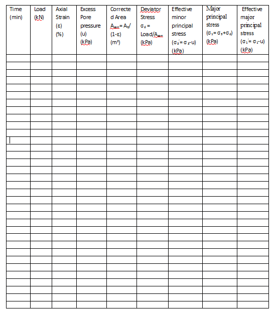
Calculations:
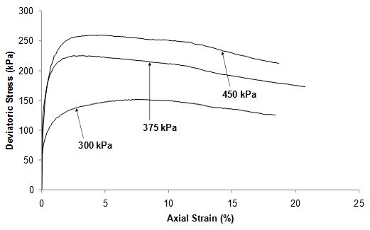
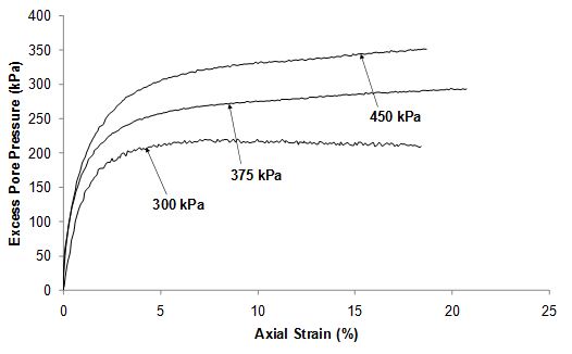
- Deviator stress versus Axial strain curve and Excess pore pressure versus axial strain curves are plotted for all three CU triaxial tests.
- The failure point of soil specimen can be defined as the point of peak stress in stress-strain relationship of each test.
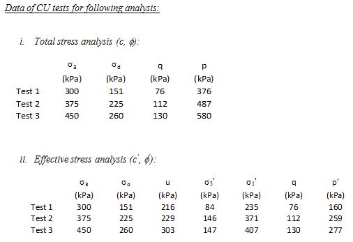
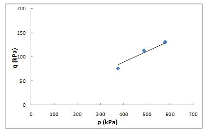
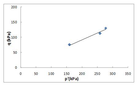
- Modified Failure envelops are obtained by drawing q-p curve for total stress analysis and q-p’ curve for effective stress analysis.
q = (σ1 – σ3)/2, p = (σ1 + σ3)/2, p’ = (σ1‘ + σ3‘)/2
σ1 = σd + σ3, σ1‘ = σd + σ3‘ - q-p curve provides a & ζ parameters. a is intercept of q-p curve and ζ is the slope angle of q-p curve. Shear strength parameters (c & Φ) can be calculated by using following equations. ccosΦ = a, sinΦ = tanζ
- Similarly q-p’ curve provides shear strength parameters (c’ & Φ’) which can be calculated by using following equations. c’cosΦ’ = a, sinΦ’ = tanζ where a is intercept of q-p’ curve and ζ is the slope angle of q-p’ curve.
Consolidated Undrained (CU) Triaxial Test
Graphs:
- Deviator stress versus axial strain curve
- Excess pore water pressure versus axial strain curve
- Modified Failure envelop (q-p) curve for Total stress analysis
- Modified Failure envelop (q-p’) curve for Effective stress analysis
Example:
CU tests have been performed on clay specimens at confining pressure of 300 kPa, 375 kPa, 450 kPa (1 kg/cm2 = 100 kPa). All the tests were performed on Normally consolidated (NC) soil specimens.
The specimens were sheared at strain rate of 0.05% per min after consolidating the specimen at chosen confining pressure. In all the tests, the saturation value B was obtained to be 0.97 before starting the consolidation phase, and the applied back pressure was 150 kPa.
Results:
Total stress analysis:
Cohesion (c) = 0 kPa
Internal friction angle (Φ) = 13 deg
Effective stress analysis:
Effective cohesion (c’) = 0 kPa
Effective Internal friction angle (Φ’) = 27 deg
General Remarks
- The isotropic consolidation process must be started after ensuring the saturation value (B) to be more than 0.95.
- The isotropic confining pressure in CU testing is applied with the drainage valve open to allow the change in void ratio of saturated soil specimen. The change in void ratio occurs due to the removal of pore water from the soil specimen during isotropic consolidation process.
- The excess pore water pressure shows positive values for NC (normally consolidated) soil specimens and negative values for OC (overconsolidated) specimens indicating contractive and dilative response respectively for saturated soils.
- The strain rate must be chosen carefully for CU test based on the soil type. The fine grained soils require to be sheared at much lower strain rate (0.05% per min – 0.2% per min) as compared to the coarse grained soils (0.5% per min – 1% per min). Fine grained soil has lower permeability (lower void space), thus pore water pressure distribution will not be uniform at higher strain in such soils (clay, silt).
- Filter paper strips can also be used around the cylindrical surface of the soil specimen to allow radial drainage to improve the drainage conditions, specially in clayey soils.
Consolidated Undrained (CU) Triaxial Test
Theory:
CU test is carried out on all types of soils. Drainage is allowed only during the isotropic consolidation, thus allowing the specimen to consolidate. At the end of consolidation, there will be no excess pore water pressure, and the specimen is ready for shearing. When the additional vertical stress (Δσ) is applied, drainage is not allowed, and thus the specimen is loaded under undrained conditions at appropriate strain rate (0.05% per min to 1% per min; clayey soil to sandy soils respectively). During the undrained loading, development of excess pore water pressure is measured continuously throughout the loading. The total and effective stresses are different at failure, and separate modified failure envelopes are drawn in terms of total and effective stresses. The CU test gives c’ and Φ’ for effective stresses and c and Φ for total stresses. The total stress parameters c and Φ are of smaller values as compared to effective stress parameters (c’ and Φ’).
The following sketch shows the three various phases of CU triaxial testing; sampling stage, Isotropic loading stage (application of confining pressure, σ3), shearing stage (application of deviator stress, σd). Total stress, pore pressure and effective stresses are shown at each phase of CU triaxial testing in the given diagram. ur is the residual pore water pressure entrapped inside the soil specimen after its collection from soil site using UDS (Undisturbed specimen) tube. σv and σh are the vertical and horizontal stresses respectively acting on soil specimen during UU triaxial testing. A is the pore pressure parameter due to the shear deformation of the soil specimen.
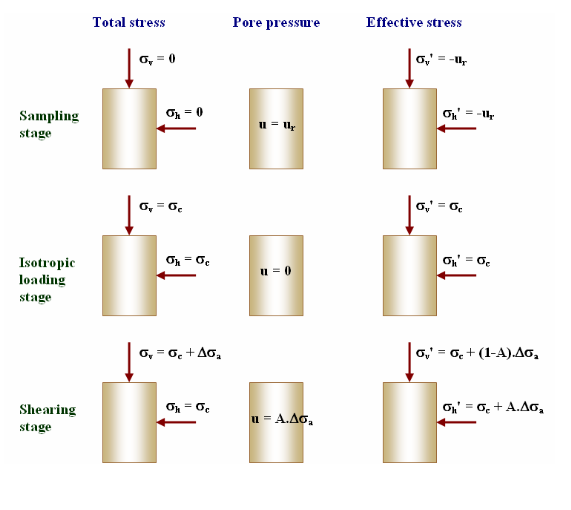
Residual pore pressure (ur) is contained inside the specimen during the sampling stage, which gets dissipated when drainage valves are open during the saturation process (CO2 saturation, water saturation and application of back pressure). After acquiring the saturation value (B) more than 0.95 (which corresponds to 95% saturation of soil specimen), the confining pressure is applied for isotropic consolidation and generated pore water pressure due to confining pressure also dissipates since drainage valves are kept open during the consolidation stage. Thus, pore pressure shows zero during second stage, isotropic loading stage (u=0). Shearing stage is started after the consolidation process is over. Shear deformation stage of isotropically consolidated soil specimen shows excess pore pressure (u), which exhibits the pore pressure evolution within the soil mass due to load subjected to specimen at applied strain rate.