Consolidation Test
Need and Scope:
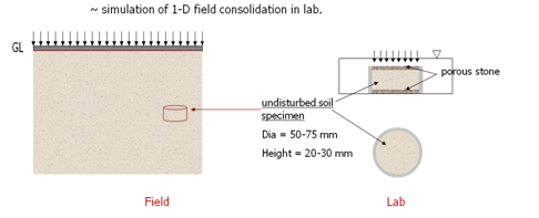
This test simulates one dimensional primary consolidation with double drainage. The following parameters are determined by conducting Consolidation test on fine grained soils:
- Pressure-void ratio relationship
- Compression and Recompression index
- Coefficient of consolidation at various pressures
- Preconsolidation pressure
- Degree of consolidation at any time
- Rate of consolidation under vertical loads
The above information can be used to predict the time rate and extent of settlement of structures founded on fine-grained soils. It is also helpful in analyzing the stress history of soil.
Concept:
The gradual process which involves, simultaneously, a slow escape of water and a gradual compression, and which will be shown later to involve also a gradual pressure adjustment, is called consolidation. It is merely compression under a steady static pressure where the soil particles attain a closer packing due to sliding and rolling of particles as water escapes from the voids.
When a compressive load is applied to soil mass, a decrease in its volume takes place, the decrease in volume of soil mass under stress is known as compression and the property of soil mass pertaining to its tendency to decrease in volume under pressure is known as compressibility. In a saturated soil mass having its voids filled with incompressible water, decrease in volume or compression can take place when water is expelled out of the voids. Such a compression resulting from a long-time static load and the consequent escape of pore water is termed as consolidation. When the load is applied on the saturated soil mass, the entire load is carried by pore water in the beginning. As the water begins escaping from the voids, the hydrostatic pressure in water gets gradually dissipated and the load is shifted to the soil particles which increases effective stress on them, as a result the soil mass decrease in volume. The rate of escape of water depends on the permeability of the soil.
SAMPLE PREPARATION:
1. Undisturbed sample:
From the sample tube (Shelby tube), eject the sample into the consolidation ring. The sample should project about one cm from outer ring. Trim the sample smooth and flush with top and bottom of the ring by using wire saw. Clean the ring from outside and keep it ready for weighing.
2. Remolded sample:
-
- Choose the density and water content at which sample has to be compacted from the moisture-density curve, and calculate the quantity of soil and water required to mix and compact.
- Compact the specimen in compaction mould in three layers using the standard rammers (moist tamping technique).
- Eject the specimen from the mould using the sample extractor.
Consolidation Test
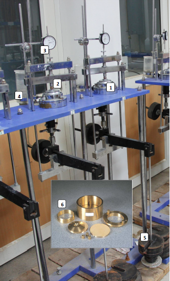
Experimental Setup:
- Soil specimen with consolidation setup
- Steel ball
- Dial gauge (for displacement measurement)
- Water reservoir (to keep soil specimen saturated)
- Loads (for application of vertical stress)
- Consolidation ring (used for extracting undisturbed soil sample)
Testing Procedure (IS 2720 Part 15):
The consolidation test is carried out using oedometer setup. The Oedometer setup consists of a consolidation cell, i.e., loading device and cylindrical container. The soil sample is loaded in increments of vertical stress. Under each stress increment, the sample is allowed to consolidate till there is little or no further change in dial gauge reading.
- Saturate two porous stones either by boiling in distilled water about 15 minute or by keeping them submerged in the distilled water for 4 to 8 hrs. Fittings of the consolidometer which is to be enclosed shall be moistened.
- Assemble the consolidometer, with the soil specimen and porous stones at top and bottom of specimen, and providing a filter paper between the soil specimen and porous stone.
- Position the pressure pad centrally on the top porous stone. Mount the mould assembly on the loading frame, and center it such that the load applied is axial. Make sure that the porous stone and pressure pad are not touching the walls of mould on their sides.
- Position the dial gauge to measure the vertical compression of the specimen. The dial gauge holder should be set so that the dial gauge is in the beginning of its releases run, and also allowing sufficient margin for the swelling of the soil, if any.
- Fill the mould with water and apply an initial load to the assembly. The magnitude of this load should be chosen by trial, such that there is no swelling. It should be not less than 50 gm/cm2 for ordinary soils & 25 gm/cm2 for very soft soils. The load should be allowed to stand until there is no change in dial gauge readings for two consecutive hours or for a maximum of 24 hours.
- Note the final dial reading under the initial load. Apply first load of intensity 0.1 kg/cm2 (Approx.) and start the stop watch simultaneously. Record the dial gauge readings at various time intervals. The dial gauge readings are taken until 90% consolidation is reached. Primary consolidation is gradually reached within 24 hrs.
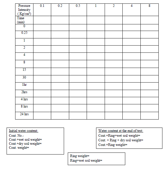
- At the end of the period, specified above take the dial reading and time reading. Double the load intensity and take the dial readings at various time intervals. Repeat this procedure for successive load increments. The usual loading intensity is as follows (Approx.): 0.1, 0.2, 0.5, 1, 2, 4 and 8 kg/cm2.
- On completion of the final loading stage, the specimen shall be unloaded by pressure decrements which decrease the load to one-fourth of the last load. Dial gauge readings may be taken as necessary during each stage of unloading. If desired, the time intervals used during the consolidation increments may be adopted; usually it is possible to proceed much more rapidly (IS 2720- Part 15).
- In unloading phase, the load needs to be reduced in the reverse order (8, 4, 2, 1, 0.5, 0.2 and 0.1 kg/cm2) and allow it to stand for 2 hrs. Take the final reading of the dial gauge.
- Quickly dismantle the specimen assembly and put the soil specimen in oven for 24 hours, take its dry weight.
Consolidation Test
Observation Sheet:
Table I: Data Sheet for Consolidation Test: Time- Displacement Relationship
Ring Dimensions: Diameter: ——————- Area: ————- Height: ————–
Initial Data: Specimen Ht: —————- Specific Gravity of Soil (GS): ———–
Mass of top porous stone + cap + ball bearing:————

Calculations:
1. Height of solids (HS) is calculated from the equation
HS = WS/(GS.γw.A)
2. Void ratio. Voids ratio at the end of various pressures are calculated from equation
e = (H – HS)/HS
3. Coefficient of consolidation. The Coefficient of consolidation at each pressures increment is calculated by using the following equations :
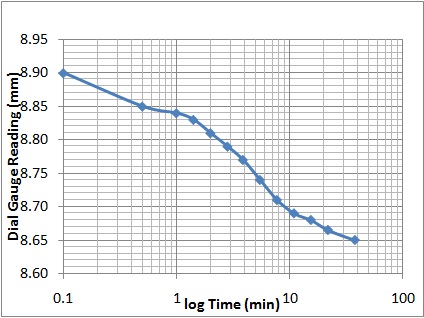
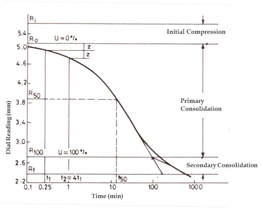
i. Cv = 0.197 d2/t50 (Log fitting method; Casagrande Method)
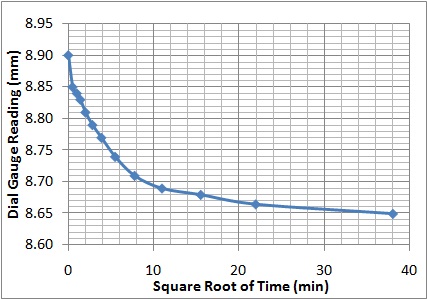
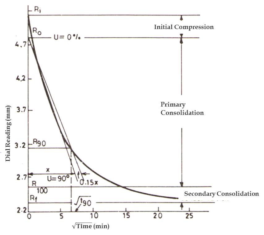
ii. Cv = 0.848 d2t90 (Square fitting method; Taylor Method)
In the log fitting method, a plot is made between dial readings and logarithmic of time at constant load, and the time corresponding to 50% consolidation is determined.
In the square root fitting method, a plot is made between dial readings and square root of time at constant load, and the time corresponding to 90% consolidation is determined. The values of Cv are recorded .
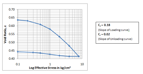
4. Compression Index. To determine the compression index, a plot of voids ratio (e) Vs log(t) is made. The virgin compression curve would be a straight line and the slope of this line would give the compression index Cc.
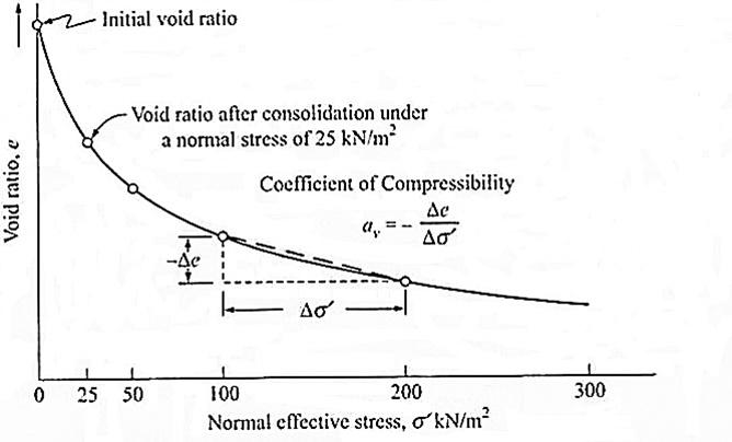
5. Coefficient of compressibility. It is calculated as follows av = 0.435 Cc/(Avg. pressure) for the increment where Cc = Coefficient of compressibility
Or, av can be also obtained by using void ratio versus pressure curve, which will be a function of pressure.
6. Coefficient of permeability. It is calculated as follows
k = Cv.av .γw /(1+eo).
Consolidation Test
Graphs:
- Dial reading VS log of time or
- Dial reading VS square root of time.
- Voids ratio VS logp (average pressure for the increment).
e-log(t) curve
Settlement versus time curve for 50 kPa pressure using Taylor method (sqrt time) Settlement
Settlement versus time curve for 50 kPa pressure using Casagrander method (log time)
General Remarks
- While preparing the specimen, attempt has to be made to have the consolidation apparatus orientated in the same direction in the soil strata.
- During trimming care should be taken in handling the soil specimen with least pressure.
- Smaller increments of sequential loading have to be adopted for soft soils.
Consolidation Test
Terzaghi’s Theory of Consolidation: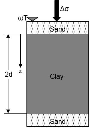
The assumptions considered to establish the basic relationship are as follows:
- Soil is homogenous, isotropic and fully saturated.
- Soil grains and water in the voids are incompressible.
- Permeability remains constant during the entire period of consolidation.
- Darcy’s law is valid throughout the consolidation process.
- Soil is laterally confined.
- Compression and fluid flow are only in axial direction.
- Time lag in consolidation is entirely due to the low permeability of soil.
- Unique relationship (Linear) is assumed between void ratio and the effective stress, and this remains constant during the load increment.
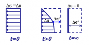
The equilibrium of an element at a depth z from its top at time t is being considered and using darcy’s law, the following differential equation has been derived for one-dimensional consolidation:

where, u is the excess hydro-static pressure and cv is coefficient of consolidation.
The solution of this differential equation is obtained through Fourier series and separation of variable method. Depending upon the boundary conditions,
t = 0, u = u0 , for any value of z (u0 is initial hydrostatic pressure)
t = ∞, u = 0 , for any value of z
z = 0, u = 0 , for any value of t
z = H (=2d), u = 0 , for any value of t
The solution of this equation is:
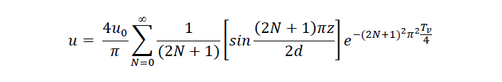
Where, Tv is time factor and directly proportional to elapse time for consolidation = cvt/d2. Its value will be different for different drainage conditions.
Drainage Paths:
It is maximum distance that water has to travel before reaching free drainage conditions.
Single Drainage or Half-Closed Layer:
Drainage will occur from one side (top in below figure) and other will remain impervious. The value of d (drainage path) is equal to thickness of layer.
Double Drainage or Open Layer:
Drainage will occur from both side.The value of d (drainage path) is equal to half the thickness of layer.

Limitations of Theory:
The presence of air may affect the results abruptly.
Permeability decreases as consolidation progresses due to increase in the effective stress.
Darcy’s law is not valid at very low hydraulic gradients.
In the field, consolidation is 3-D not 1-D.
The relationship between void ratio and effective stress is not linear.
It is noted that error due to this assumption is not very large and these can be accepted to get a relatively simple expression.
Determination of coefficient of consolidation (Cv):
1. Casagrande Method (logt method)
2. Taylor Method (√t method)
Settlement curve (oedometer test at each pressure/load):
Casagrade method : t50 (U = 50%)
Tayor method : t90(U = 90%)
U = Degree of consolidation
T = Time factor
Ht = Depth of the sample
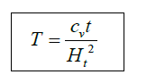
Coefficient of consolidation (cv) can be determined using above equation.
Coefficient of compressibility (av ) can be obtained by using void ratio versus effective stress relationship.
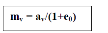
where, mv is coefficient of volume compressibility and e0 is initial void ratio.

where, γw is unit weight of water and k is permeability of soil specimen.
Settlement calculations:
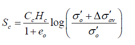
Compressibility parameters Cc & Cr are used in settlement calculations. Cc is the slope of loading curve and Cr or Cs is the slope of unloading curve.
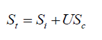
where Si is immediate settlement and Sc is settlement due to consolidation, which can be obtained by oedometer test. St is total settlement and U is degree of consolidation.
Settlement for NC soil
Settlement for OC soil
