Bender Element Test
Need and Scope:
Determination of small strain shear modulus of soils in the laboratory by propagating a shear wave through the specimen, measure its velocity, and calculate the small strain shear modulus using density & shear wave velocity of the material. Shear waves can be generated and measured by small pieces of piezoceramic called bender elements, which can be installed at the end caps of specimens in commonly used triaxial setup. The piezoceramic bender element is an electro-mechanical transducer, which is capable of converting mechanical energy either to or from electrical energy.
Concept:
Shear wave velocity determination in sands is important for analyzing and predicting safety of various structures located on it. The initial tangent shear modulus (Gmax) of soil, also termed as small strain shear modulus of soil, is a fundamental parameter used in various kinds of geotechnical analysis especially in earthquake geotechnical engineering and soil dynamics. There is an increasing interest in using small strain shear modulus to define the state of sand so as to use non-destructive techniques for site characterization. The value of shear modulus depends on a number of parameters, including void ratio, confining stress, soil structure, degree of saturation, temperature, stress history, and time.
At strains within the elastic range, typically 10-4% or less, the stiffness is represented by shear wave velocity, and in turn small strain shear modulus. This parameter is useful for the design and analysis of earthquake resistant foundations, vibrating machine foundations, vibration isolation measures, analysis of soil-structure interaction problems and design of shallow and deep foundations. Some of the real life situations, where these studies are of great importance are: impact of an earthquake on structures such as buildings, roads, embankments, railway track formations, monitoring soil stabilization,
The strain level in engineering structures lies in the small strain range, and thus the small-strain modulus (Gmax) of geotechnical fill materials is a key parameter in defining the material response to static loading. It is now treated as a fundamental property of soil. Gmax is also important in small-strain dynamic analyses such as those used to predict soil behaviour during earthquakes, explosions, or machine and traffic vibrations.
Bender Element Test
Experimental Setup:
The bender element system is comprised of the following components:
- Two bender elements inserts with adopted top cap and pedestal
- External control box
- Bender element with specimen inside the triaxial cell
- High speed computer data acquisition and control card
- Windows based Bender element system control and acquisition software
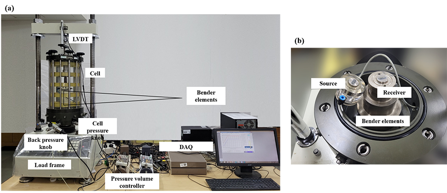
Automated stress-path triaxial setup with Bender element system
Testing procedure:
Piezoceramics have the ability to convert electrical impulses to mechanical impulses and vice versa. When a voltage impulse is applied across a single sheet of piezoceramic, it will either shorten or lengthen with a corresponding increase or decrease in thickness. If two piezoceramic sheets are mounted together with their respective polarities opposite to each other, an electrical impulse will cause one side to lengthen and the other side to shorten (as shown in figure presenting transmission of S wave). The net result of this will be a bending of the two sheets, hence the name bender elements. Thus, if an electrical impulse is sent to a bender element (transmitter) mounted in the bottom cap of a specimen, the bender element will produce a small “wiggle” and generate a shear wave that will propagate up through the soil. When the shear waves reach the top of the specimen they cause the bender element mounted in the top cap (receiver) to vibrate slightly, thus creating an electrical impulse.
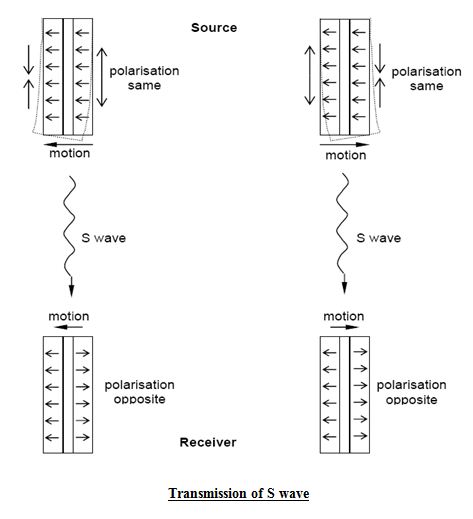
The S-wave produced by the source bender element is polarized. That means the receiver is placed at 90 degrees to the source (out of line), then theoretically no signal will be received. For maximum signal to be acquired, the receiver should be oriented exactly in the same direction as the source (in-line). In the soil application, the bender elements are encapsulated and mounted into inserts, which are fixed into the pedestal and top cap of a triaxial cell.
Typically, bender elements protrude 3 mm into each end of the specimen. When excited the bender element bends from side to side pushing the soil in a direction perpendicular to the length of the element and thus having a large coupling factor with the soil. This produces a shear wave, which propagates parallel to the length of the element into the soil specimen. On the other end of the soil specimen, another bender element is forced to bend and produces an electrical signal that can be measured. The input and output electric signals are recorded on the computer for subsequent analysis. Computer-screen is used to observe both the impulses, the one sent to the transmitter and the other one generated by the receiver. Bender Element software is used for configuring the elements, generating source wave, and acquiring signal from the receiver.
The small strain shear modulus using bender element method can be determined from the theory of elasticity using following equation.
Gmax = ρVs2
Where, Gmax = small strain shear modulus, ρ = material density, and Vs = shear wave velocity.
Bender Element Test
Data Analysis:
The travel length of the wave is considered to be the length of the specimen minus the length of the bender elements (mid-to-mid distance). The shear wave velocity is then calculated by dividing the corrected length (Le) by the travel time of the wave from the transmitter to the receiver (t), or
Vs = Le / t
In case the bender element test is performed with triaxial testing, the length of the specimen changes during shearing and hence the travel length of the wave will also change with axial deformation of the specimen. The corrected length of travel at any stage of measurement can be obtained using the following equations.
ΔLt = ε * L
L0 = L – ΔLt
Le = L0 -Δe
Here, L = total length of the triaxial sand specimen, Δe = effective height of tip of the transducer, L0 = the length between the tips of the transducers, Le = Effective length of wave propagation with increasing strain rate, and ε = Axial strain.
There are four methods which have been suggested in the literature for computing the travel time of the wave through the soil specimen: (i) first arrival time, (ii) travel time between the characteristic points, (iii) cross-correlation of input and output signals, (iv) cross-power spectra of transmitter and receiver signals. First arrival time was defined as the travel time to the first arrival of the receiver signal. Some researchers have taken first arrival as first deflection point of the receiver signal. Due to the difficulties in precisely determining first arrival time, some of them calculated travel time based on characteristic points given by peaks or troughs of the transmitter and receiver signals. It was also reported that use of characteristic points to determine travel time was only acceptable at high frequencies. In the cross-correlation between transmitter and receiver signals, the travel time was taken as the time shift that produces the peak cross-correlation between the input and output signals. A group travel time of the wave for a range of frequencies between the transmitter and receiver elements can be determined by linear interpolation of the absolute cross power spectrum phase diagram. A few researchers concluded that travel time could not be reliably determined from the first arrival time of the receiver signal due to near field effects, the most accurate travel time was given by the cross-correlation or the cross-power of the transmitter and the use of characteristic points to determine travel time was a simple alternative method.
Bender Element Test
Example:
Example: The small strain shear modulus of Ganga sand was determined by performing bender element test during consolidated undrained (CU) Triaxial tests using bender elements (peizoceramic pieces) at top and bottom of the soil specimen. Shear waves were generated and propagated through the bottom of the specimen, and then measured the signal at the top end of the specimen. Bender element measurements were taken at every 2% of axial strain during shearing. The applied sinusoidal pulse was having frequency of 500 kHz , time period of 0.1 ms and amplitude of 14 V.
The figure below shows typical results of input, output and cross-correlated signals of shear wave with time period 0.1 ms. During the Bender element test, the initial mean effective stress, pi’ was kept to be 500 kPa. In this figure input signal showed in dotted line, output signal showed with thinner line and cross-correlated line showed with thicker line. The travel time of the waves determined by two methods have been compared in (i) the travel time (tm = 0.39) was determined from the delay time denoted as BB’ in the figure. BB’ was the period between the beginning of the input pulse and the arrival of the wave on the receiver.(ii) travel time determined by cross-correlation (tcc =0.45) method that fits at best the input and the output signals. The delayed time tm over estimated shear wave velocity here. The cross-correlation method provided a reliable indication of the travel time for greater frequencies which increased with the pi’.
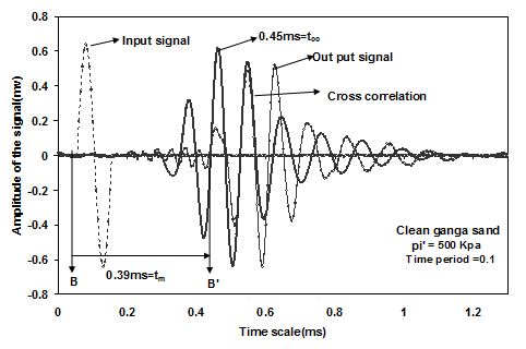
Typical Bender Element test results: Input, Output and cross-correlated signals
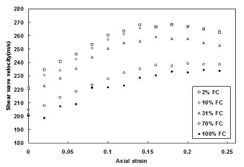
Shear wave velocity vs. axial strain of Ganga sand with silt content (FC)
General Remarks
- Bender elements must be handled with care. Improper handling may cause the protective waterproof cover of the element to be damaged.
- For stiff specimens it may be necessary to create a cavity for the element in the specimen ends so as not to damage the elements during mounting or testing. The cavity may be filled with a suitable filler to allow good coupling between the element and specimen.
- It is very important to ensure that the source and the receiver are aligned parallel to each other.
Bender Element Test
Theory:
A shear wave is an elastic body wave, meaning it is a wave that travels within an elastic medium, whose direction of propagation is perpendicular to its direction of particle displacement. A compression wave is another type of elastic body wave, however, its direction of propagation is parallel to its direction of particle displacement. Although both types of body waves can propagate through soils, the shear wave exhibits some properties that make it more applicable for studying soils. First, in a saturated soil (a two-phase porous medium), shear waves propagate only through the solid phase, because water can not support shear stresses.
Several laboratory techniques have been developed to measure directly the small strain shear modulus, such as the torsional resonant column and cyclic torsional shear technique. It must be noted that resonant column tests can only be performed in especially designed apparatus, which is not only expensive but large in size too. Apart from this, most of these methods are extremely cumbersome , indirect, employ cost intensive instrumentation and necessitate skilled manpower.
Bender element systems can be set up in most laboratory apparatus. They are particularly versatile when used in the triaxial test. In addition, generating shear waves and measuring the small strain shear modulus does not change the properties of the specimens, and is thus considered to be a non-destructive test. Therefore, small strain shear modulus measurements can be made throughout testing without causing any disturbance to the specimen.
The system uses a pair of piezo-electric bender elements, a source and a receiver, to send body waves through a soil specimen. A piezoelectric material generates electrical output when subjected to mechanical deformation or vice versa and changes its shape when an electrical field is applied to it. Piezoelectricity can be found in nature in quartz and tourmaline crystals. In industrial applications, it is often obtained artificially with certain ceramics such as lead zirconate titanate, barium titanate, and lead titanate. Activation of the piezoelectric property in ceramics, typically called polarization, is obtained by applying a high d-c voltage between a pair of electrode faces. The way a polarized ceramic element deforms depends on the following: ceramic shape and composition, direction of the polling axis, and location of the applied electrical field.